Back to Contents Page
Technical Overview
Dell Dimension 2400 Series
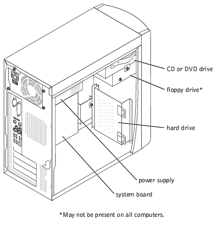
 Looking Inside Your Computer
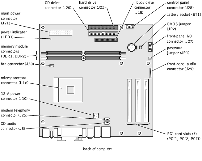
System Board Components
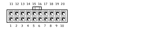
Power Supply DC Connector Pin Assignments
Looking Inside Your Computer

|
CAUTION: Before you begin any of the procedures in this section, follow the safety instructions in your Owner's Manual or Product Information Guide. |
|
|
CAUTION: To guard against electrical shock, always unplug your computer from the electrical outlet before opening the computer cover. |
System Board Components
Power Supply DC Connector Pin Assignments
DC Power Connector P1
|
Pin Number
|
Signal name
|
18-AWG Wire
|
|---|
1 | +3.3 VDC | Orange |
2 | +3.3 VDC | Orange |
3 | COM | Black |
4 | +5 VDC | Red |
5 | COM | Black |
6 | +5 VDC | Red |
7 | COM | Black |
8 | POK* | Gray |
9 | +5 VFP | Purple |
10 | +12 VDC | Yellow |
11 | +3.3 VDC | Orange |
12 | –12 VDC* | Blue |
13 | COM | Black |
14 | PS ON* | Green |
15 | COM | Black |
16 | COM | Black |
17 | COM | Black |
18 | - | No connect |
19 | +5 VDC | Red |
20 | +5 VDC | Red |
*Use 22-AWG wire instead of 18-AWG wire. |
DC Power Connector P2

|
Pin Number
|
Signal Name
|
18-AWG Wire
|
|---|
1 | COM | Black |
2 | COM | Black |
3 | +12 VDC | Yellow |
4 | +12 VDC | Yellow |
DC Power Connectors P3, P5, P6, P8 and P9

|
Pin Number
|
Signal Name
|
18-AWG Wire
|
|---|
1 | +12 VDC | Yellow |
2 | COM | Black |
3 | COM | Black |
4 | +5 VDC | Red |
DC Power Connector P4

|
Pin Number
|
Signal Name
|
22-AWG Wire
|
|---|
1 | - | No connect |
2 | COM | Black |
3 | COM | Black |
4 | +3.3 VDC | Orange |
5 | +5VDC | Red |
6 | +12VDC | Yellow |
DC Power Connector P7

|
Pin Number
|
Signal Name
|
22-AWG Wire
|
|---|
1 | +5 VDC | Red |
2 | COM | Black |
3 | COM | Black |
4 | +12 VDC | Yellow |
Back to Contents Page